Infinite
Energy Device Update
Published in IE Volume
6, Issue #36, March-April, 2001
First
Gate Energies’ Sonofusion Reactor:
Initial Validation at 50% Excess Heat
Success is especially sweet when one has been trying for a
long time, without much success, to identify and develop a robust demonstration
device for cold fusion phenomena—excess heat and nuclear effects. Such a device
now appears to be close at hand in the sonofusion reactor of Roger Stringham and
his colleagues at First Gate Energies. In mid-February Ken Rauen, as lead
investigator, succeeded in reproducing the approximate excess heat results that
Stringham had obtained in the same reactor when it was in his California lab
(see IE, No. 35, p. 21, p. 70).
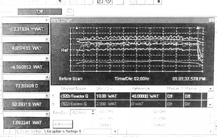
Figure 1 is a sample of one stretch of excess
power, varying with the unknown conditions on the surface of a copper foil
target in heavy water. This was under pulsed acoustic dual-transducer activation
with approximately 40 kHz wave packets.
 |
Figure 1. Sample of one stretch of excess power. The exess heat line is marked with an arrow and appears darker than the adjacent lines. The "Ref" line on the Y axis is zero watta excess heat. Vertical scale is 2 watts/division. The cyclic fluctuations are due to furnace cycling to keep the lab warm, as it is winter in New Hampshire. |
With a margin of error in the preliminary result that we believe
to about ±0.5 watt (certainly no more than
±1 watt), we have high confidence that excess heat has been faithfully
reproduced. We have confidence in the joule heater
calorimetric calibration of both the input acoustic signal oscillator electronics
and the reactor itself, which has a built-in joule heater calibration. Given
the experience of Stringham in producing similar results on demand over many
years, we believe this is an excellent candidate to be a robust demonstration
of cold fusion phenomena. Many
new experiments need to be performed, including attempts to reduce or zero the
excess heat by employing ordinary water and some other metals, reducing argon
pressure, lowering input power below a critical value, etc. (The excess heat is said to be so frequently
part of any such sonofusion reactor work, that in this instance the best “null”
is found by cross checks on the calorimetry; we have already carried these out.)
Though much work remains to be done in getting onto market with this scientific
demonstration device, First Gate Energies has agreed to allow NERL to be the
exclusive developer, marketer, and distributor of scientific demonstration educational
kits based on Stringham’s “M3S” sonofusion reactor. (Those who would consider obtaining such
a research kit are asked to contact NERL as soon as possible, to establish priority
and help us anticipate production runs. Note well: We will not distribute such
kits until we are certain that we can guarantee excess heat results on demand.)
 |
|
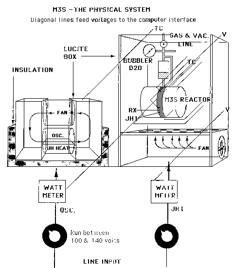
Figure 2a. Set-up schematic of sonofusion reactor. |
The road to successful confirmation was not easy. After Eugene Mallove’s visit
last fall to the First Gate Energies laboratory in California, Roger Stringham
sent to NERL in Bow, New Hampshire the M3S sonofusion reactor, its Plexiglas
test stand, and its transducer electronics calorimeter. The set-up can be seen
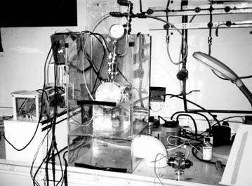
schematically in Figures 2a and 2b. A picture of the full system at NERL with
our Toshiba laptop computer data acquisition system appears in Figure 3 while
it was producing excess heat on February 17. The reactor seals had developed
leaks from prolonged use by Stringham and perhaps from the transport. During
various stages of replacing seals, leaks and input power losses occurred, in
one case due to ultrasonic power absorption in soft-rubber replacement seals;
we reverted to Teflon seals.
Our data acquisition system software is BenchlinkTM (by Agilent/HP),
which allows up to twenty-two channels of thermocouple and input power measurements
via an Agilent/HP 34970a Data Acquisition Switch Unit, which periodically
scans all input channels.
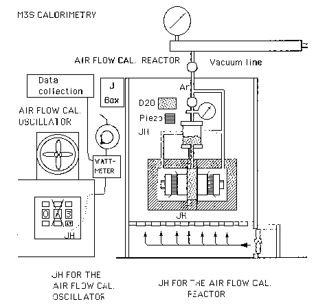 |
| Figure 2b. Set-up schematic of sonofusion reactor. |
The very first run of the sonofusion reactor, with the new teflon
gaskets, produced excess heat with good confidence. The excess power was initially
2.5W, with about 5W of ultrasonic energy into the reactor (5 watts in, 7.5 watts
out). From the calibration runs
and from two control tests during the run, we are confident that the error margin
of this experiment is about 6 0.5W.
As a confidence check, Ken Rauen turned off the oscillator electronics and moved
the oscillator cooling loop thermocouple from the calorimeter box to the piece
of steel which houses the ambient temperature recording thermocouple; there
was a mere 0.15°C difference. The associated excess heat error is no more than
+/- 0.2W, as expected in this zeroing of input. Later, after a day or more of
operation, the excess heat increased to a higher level—up to 8 watts, but it
also dipped periodically, though never approaching zero. We know that for an
unknown reason reactor calibration changed, so our confidence in the 100% figure
is not good.
The thermocouple was then replaced into the oscillator electronics calorimeter
with oscillator power off. The oscillator calorimeter without its circulation
fan cools very slowly. It was allowed to run overnight to see
if the temperature difference would drop to zero. It went to 0.2°C, which results in about
0.5W of excess heat calculated. We
discount this zero check, as the offset is not an offset in the heat calculation;
the equation is nonlinear. The
placement of the two thermocouples in the same environment is a better check
of the system in our opinion. The
next step was to increase the reactor heater power to reach temperatures seen
by Roger Stringham as necessary for good performance. The first excess heat run was about 95
to 100°C, possibly too cold for optimal cold fusion. Better results were found
at 108°C.
We intend to redesign the system for the educational kit such that an accurately
known bias joule heater power of over 50 watts is not required to keep the reactor
at operating temperature. This can be done by appropriate insulation to make
the reactor self-heat. We also intend to perform gas sampling in order to detect
the helium that Stringham has previously reported emanating from this reactor.
Scientific demonstration kits will have gas sampling facility provided with
them so that gas can be sent for testing for helium at centers with quadrupole
mass spectrometers that are suitable for such refined testing.
 |
 |
|
Figure 3. Stringham set-up. |
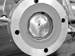
Figure 4. Thin copper target showing hole. |
A curious phenomenon occurred in initial testing, before we detected excess
heat. The thin copper target that Stringham had provided to us developed a small
hole in it! Such holes had previously
been reported in sonofusion targets, but usually with attendant visual evidence
of melting. This target (5 mil thickness) had rough edges under microscopic
examination that were unlike those in simple tearing of copper sheet of the
same thickness (see Figure 4).
Later, we observed the central perforation of the copper target with which excess
heat was detected. This time there was evidence of surface thermal and mechanical
damage. Fertile ground for investigations of many kinds.